The 'Precursor' was a 4-4-0 express locomotive introduced by the London and North Wester Railway in about 1905. This model dates from c. 1910 and has Bassett Lowke features although the exact attribution is not currently known. It was certainly professionally built to a very good standard and uses Whitworth threads, suggesting a date before 1914.
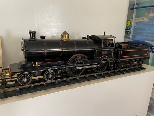
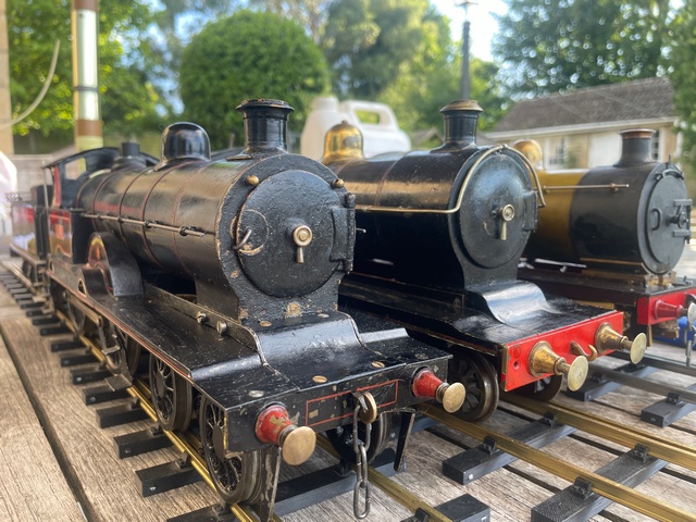
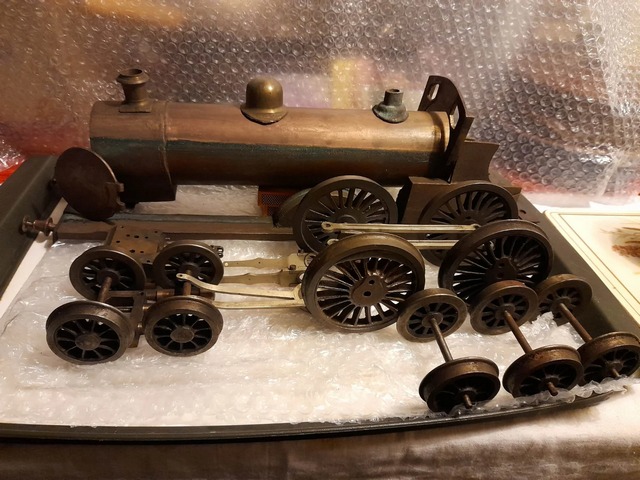
This model is similar to the Carson version but somewhat over scale. Here is a Gauge
2 Line up (Carson on left, 'mystery engine' at centre, Greenly's
'Six Coupled Tender Engine' at right):
Cab and backhead. Note the Bassett Lowke water pump,
which has been added, suggesting that the loco must have run and
run well, and the push-pull style regulator.
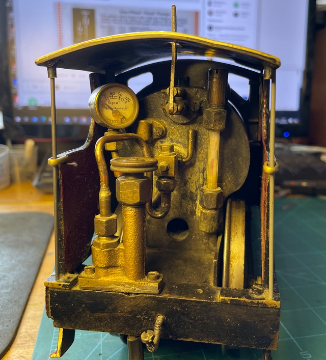
It's intriguing that the gauge glass had a red line as
in modern models. I think of this as very much a modern feature,
but all the evidence in terms of corrosion and patina points to
this being an original fitting. Sadly this 3/16" glass had to be
sacrificed in the interests of overhauling the backhead fittings
and will have to be replaced with modern 5mm glass. Note
also the Bassett Lowke style pressure gauge take-off. What can't
be seen is that one of the brass 3/32" Whit screws has already
vanished while the other jumped overboard at the sight of a
screwdriver. Proof, if you ever needed it, of brass
de-zincification over 100 years of exposure to boiler water.
Fortunately the tubeplates are in cast bronze and the barrel is
copper.
The fire hole is an unusual feature in what I now know to be a wet
backhead. Maybe it's for 'top air', or perhaps just for lighting
up?
See also the strange bent BA screw that now forms a
drawbar. There's no sign of an original drawbar on loco or tender
and I wonder if the model depended on Mr Jubb's patent 'use the
drip feed fuel pipe as a coupling" arrangement. Does this mean
that the loco is a Jubb? Having a genuine 2" gauge Jubb in the
collection, I can say that this engine is very heavily built and
most unlikely to be by the same hand.
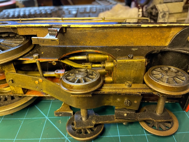
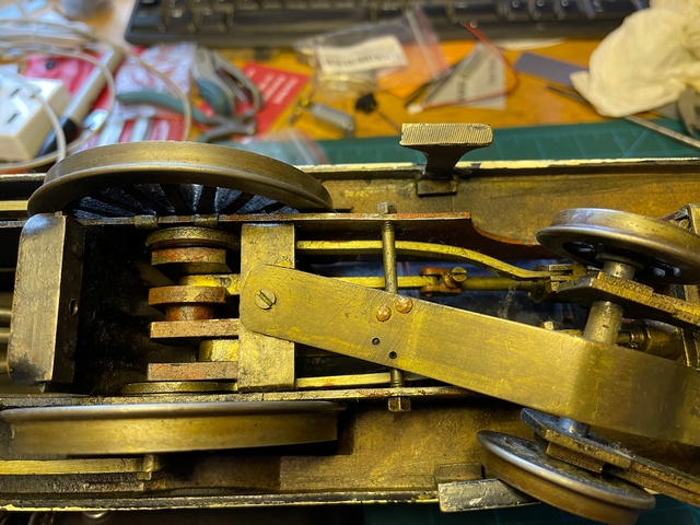
Here's a view of the underside showing the massive trunk
guide arrangement attached to the cylinder covers. Absolutely not
a Jubb (or B-L?) feature. These take the place of slide bars, a
detail that's often omitted in other models of the period leading
to premature wear. Note also the slotted gland nuts - I'm having
special spanners made for these because they sure don't want to
turn by other means! And here's the crankshaft - massively built
by the standards of the time. (The one in the Carson 'Precursor'
was buckled by mishandling when I acquired it!)
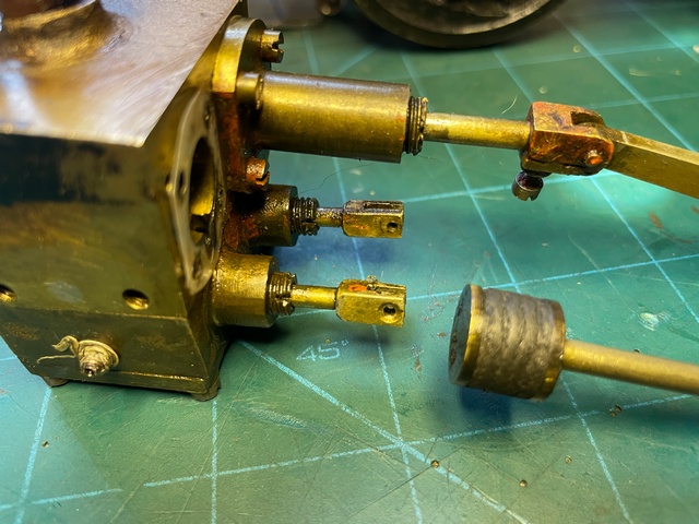
Here's a view of the cylinder block with one of the pistons
withdrawn. The bore is 1/2" and this is quite a strong engine
running on 20 psi air. Note the elaborate wound packing - soaked
in new oil, this still seems to serve perfectly well and I've not
disturbed it. (The pistons were virtually seized with old oil and
took quite a bit of cleaning up). The nipple on the side of the
block is the connection for the oil pot and is not terribly well
thought out - maybe an afterthought? All threads in this block are
Whitworth, something else that suggests it is not B-L.
See also the one piece eccentrics trapped on the axle by
pressing on the wheels - that would have needed a special press
tool, and no way of getting it apart again!
The bogie mounting is all rather crude by comparison,
perhaps to get round smaller curves, as the undersize and
underwidth bogie wheels suggest. The Carson, on the other hand,
has scale wheels and requires 10' radius curves!
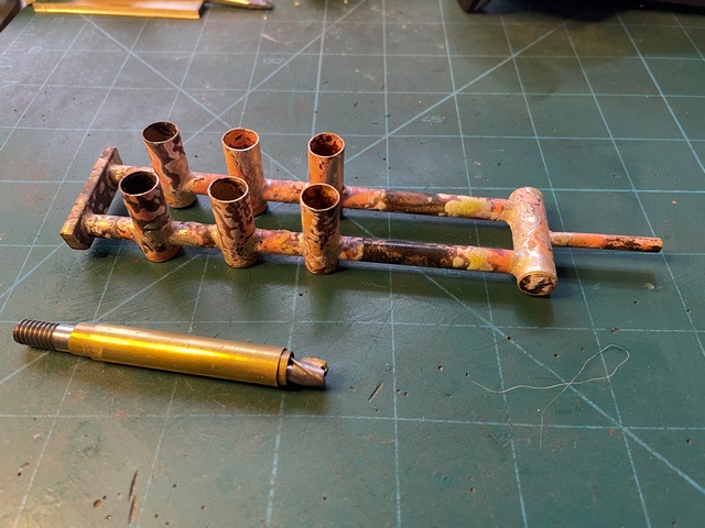
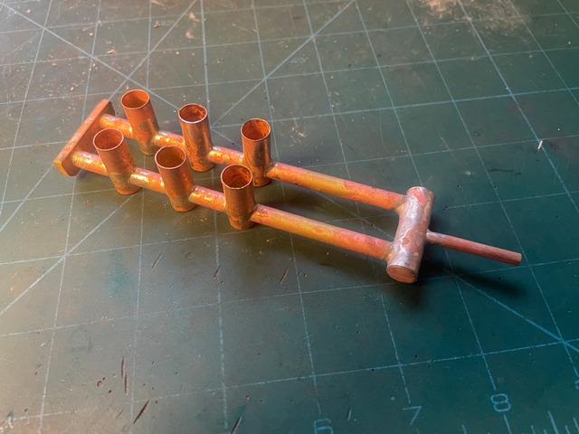
New fuel tank and Burner.
As is often the case with antique models, the burrner and
Fuel Tank were long lost. This gave the opportunity to fit a
modern, and much safer, 'chicken feed arrangement in place of what
was undoubtedly an open sump drip feed supply that could easily
overflow and catch fire. Here's the new burner for the unknown,
assumed Bassett Lowke, 'Precursor'. Made from very thin K&S
tubing for limited conductivity. Silver soldered throughout - this
is not 1910, when houses were cheap!
The wick tubes were bored through using an appropriately
sized centre drill without causing any snagging or buckling of the
thin tube. The fit is tight enough not to need any bracing during
soldering. Note shielded milling cutter for opening out the feed
tubes at the bottom of the wick holders:
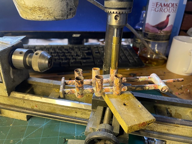
In the Unimat. Limited torque is vital because if the
cutter jams in a drilling machine, it rolls the whole thing up
into a ball. (Don't ask how I know!)
Getting closer! Next: the boiler!
Finally, who built this loco? Answers on a postcard
please ....
A footnote: another set of parts for this same model turned up on
RM web in 2023. See: https://www.rmweb.co.uk/forums/topic/178082-gauge-2-lnwr-whale-precursor-4-4-0/
These parts are identical and demonstrate that the loco was not
only commercially made, but the there was more than one! Efforts
to trace the owner of this set of parts are so far unsuccessful.